Explore current density across the test panel
Move the marker from the high-current-density edge near the anode to the low-current-density end. The app uses the commonly published 267 mL Hull Cell empirical relation J = I × (5.1 − 5.24 log₁₀x), with x in centimetres and J shown in A/dm².
Move the panel marker to explore the current-density gradient.
The test compresses a wide range of plating conditions onto one panel. A defect that appears only at one end can therefore point toward a current-density-sensitive bath problem.
Why the cell is trapezoidal
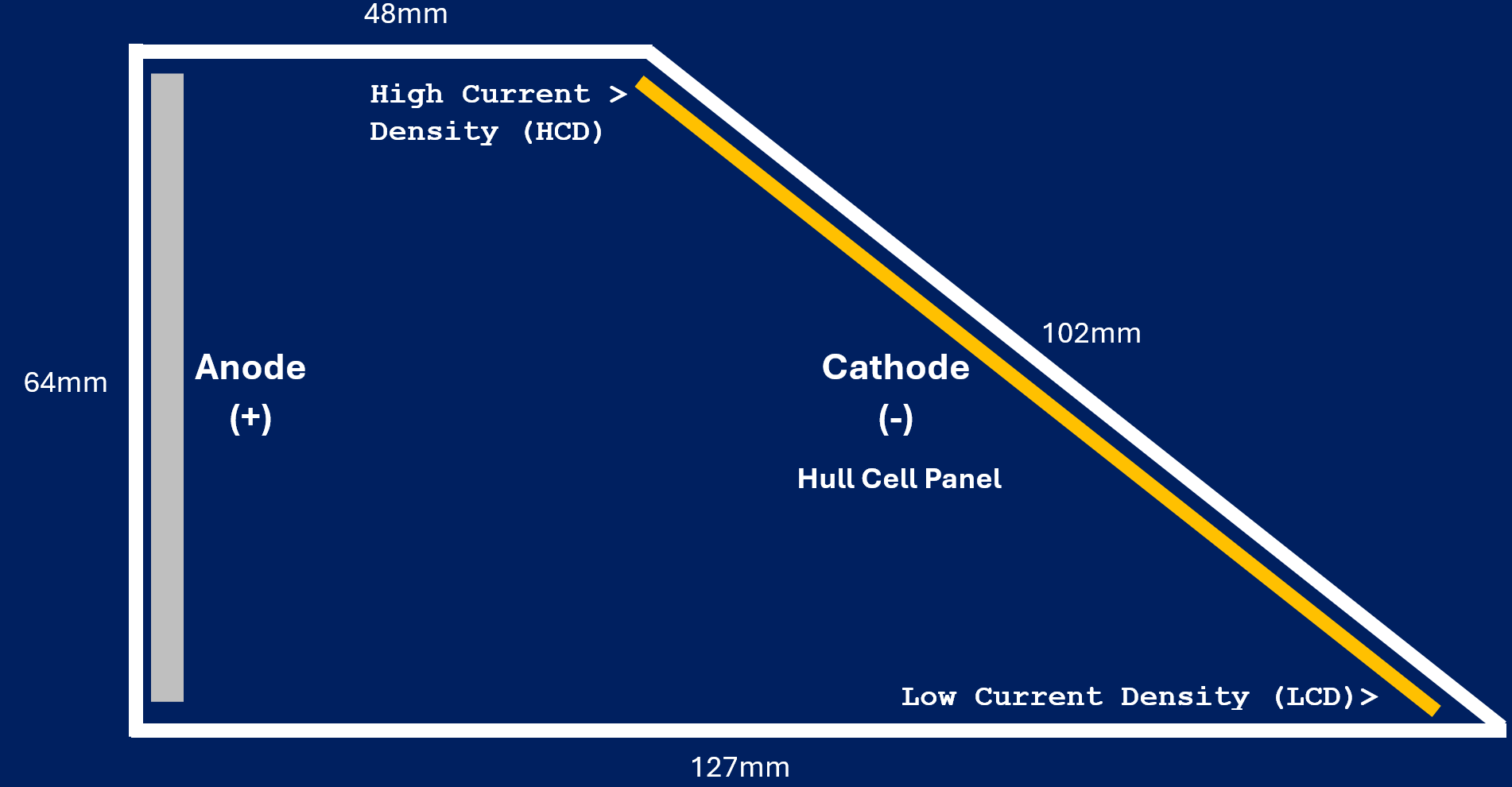
The cathode is deliberately placed at an angle to the anode. The electrical path is short at one end and progressively longer at the other. That changes solution resistance and current distribution, so one plated panel experiences a broad current-density range during a single test.
The high-current end can reveal burning, roughness or additive imbalance; the middle shows the normal decorative/engineering range; the low-current end highlights coverage, brightness and throwing behaviour. The cell therefore converts an invisible electrochemical distribution into a visible diagnostic pattern.
What a Hull Cell can show
- Usable current-density operating window
- Effects of brightener, carrier, leveler or wetter additions
- Metallic and organic contamination signatures
- High-current burning or roughness tendency
- Low-current coverage and brightness response
- Changes caused by pH, metal concentration or salts
- Comparative macro-throwing behaviour
- Whether a controlled purification treatment improves the bath
What it does not prove
It does not replace analytical chemistry, production trials, coating-thickness measurements, adhesion testing, corrosion testing or customer/specification requirements. It is a rapid comparative process-control and development tool.
Why 267 mL?
The traditional 267 mL geometry became the widely used laboratory format and supports standard rulers/current-density correlations. It also makes small controlled additions convenient for bath-development work.
Reproducibility matters
Keep sample preparation, solution volume, temperature, agitation, current, time, anode, cathode preparation and post-treatment consistent. A Hull Cell trend is only useful when the test itself is controlled.
Hull Cell, panel and current-density reference
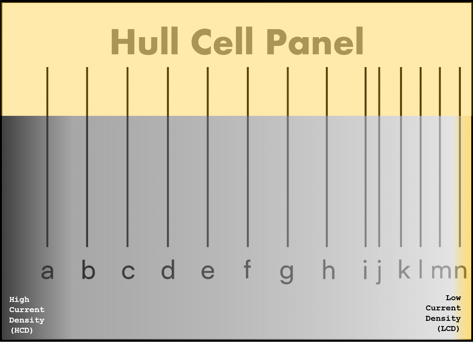
These diagrams provide the practical visual reference used alongside the interactive calculator. The cell geometry creates the current-density gradient; the panel and table then help relate a position on the plated panel to an approximate current density for common total cell currents.
Standard Hull Cell geometry

The anode and cathode are deliberately non-parallel. The short gap at the upper end of the cathode produces the high-current-density region; the progressively larger spacing towards the lower end produces the low-current-density region.
Hull Cell panel reference

Use the panel as a visual map. Read from the high-current-density end toward the low-current-density end and record where burning, brightness transitions, dullness, pitting, coverage loss or other deposit changes begin and end.
Typical current density by panel position

How to use the table: choose the row for the applied Hull Cell current, then identify the panel position. The intersection gives the typical A/dm² associated with that position. The app's live calculator provides a continuous estimate between positions using the empirical 267 mL relationship.
High current-density end
Useful for observing burning, roughness, excessive gas evolution, transport limitations and the upper end of the bright or acceptable operating range. A change appearing only here often points toward a high-current-density-sensitive condition.
Low current-density end
Useful for observing coverage, low-current brightness, throwing behaviour and the lower edge of the usable plating window. Loss of deposit or dullness that begins here can be an important clue when comparing bath condition or controlled additions.
A short history of the Hull Cell
Richard O. Hull's key idea
Hull's patent describes positioning a cathode so equal areas receive current through differently sized/length electrical paths. That made it possible to determine plating characteristics at multiple current densities in one experiment — the central idea the modern cell still uses.
Why it endured
Analytical chemistry can tell you what is in a bath, but plating behaviour is also affected by trace additives, contaminants, breakdown products and interactions. The Hull Cell gives a rapid functional view of how the solution actually deposits metal.
Plating bath reference guide
These are practical reference starting conditions compiled from Kocour's Hull Cell operating instructions, supplemented by Yamamoto-MS technical guidance. For proprietary chemistry, always use the chemical/process supplier's Hull Cell method where one is specified.
| Bath | 267 mL current | Time | Agitation | Anode | Cathode panel | Notes |
|---|
Temperature guidance
Temperature should normally reproduce the production bath or the chemistry supplier's test method. Yamamoto-MS examples include copper sulfate at room temperature to 30 °C, copper pyrophosphate at 50–60 °C and nickel at 40–60 °C. Heated processes should be tested in a controlled heated Hull Cell rather than allowed to cool during the run.
Rectifier quality
Kocour recommends a suitable low-ripple rectifier and states not to use rectifiers with greater than 3% ripple for its Hull Cell method. Poor DC quality can change deposit appearance and undermine comparison between panels.
What does your Hull Cell panel show?
Select the closest visual symptom. These are diagnostic prompts — not a substitute for the chemistry supplier's troubleshooting guide or analytical confirmation.
Recommended test workflow
Good laboratory discipline
- Use dedicated cells where cross-contamination is a risk.
- Clean the cell thoroughly between tests.
- Standardise panel material and preparation.
- Use consistent solution volume.
- Do not compare panels run at different conditions without noting the difference.
- Photograph panels under repeatable lighting.
Hull Cell addition → production bath
Enter an addition made to a 267 mL Hull Cell and your production tank volume. The calculator scales the test concentration proportionally.
Find panel position from target current density
For the 267 mL empirical relationship, enter current and target current density to estimate where that condition sits along the panel.
References used in this app
- R. O. Hull, U.S. Patent 2,149,344 — apparatus and process for studying plating solutions; filed 1935, granted 1939.
- Kocour Company — Operating Instructions for 267 & 1000 mL Hull Cells — practical bath currents, times, electrodes and operating notes.
- Yamamoto-MS — Hull Cell Technical Information — example bath conditions, temperatures, agitation and DIN 50957 references.
- Industrial Electrochemistry reference — 267 mL empirical current-density relationship and explanation of current-density range.
- DIN 50957-1 / DIN 50957-2 — referenced by Yamamoto-MS for conventional and long-type Hull Cells.
Use of data
The bath table is intended as an educational/reference starting point, not a universal process instruction. Proprietary plating chemistry can require different current, time, agitation, temperature, anodes, panels or interpretation criteria.